Author: sgeorge, Posted on: 11 July 2015 08:58
My PCBs have arrived from the fab, and they look awesome!
Here is the family portrait, first time all have been in one photo together since being redesigned. All use cat5e ethernet for rs485 communications and easy installation. each board has a jumper to set the board as the last board on the rs485 chain. the boards rs485 is designed to run at 156250 baud which is something like 20kb/s something. thats 20 bytes per 1000th of a second (basically you could send the entire 128 switch state around the bus 1000 times a second theoretically, good thing we dont need it that often!)
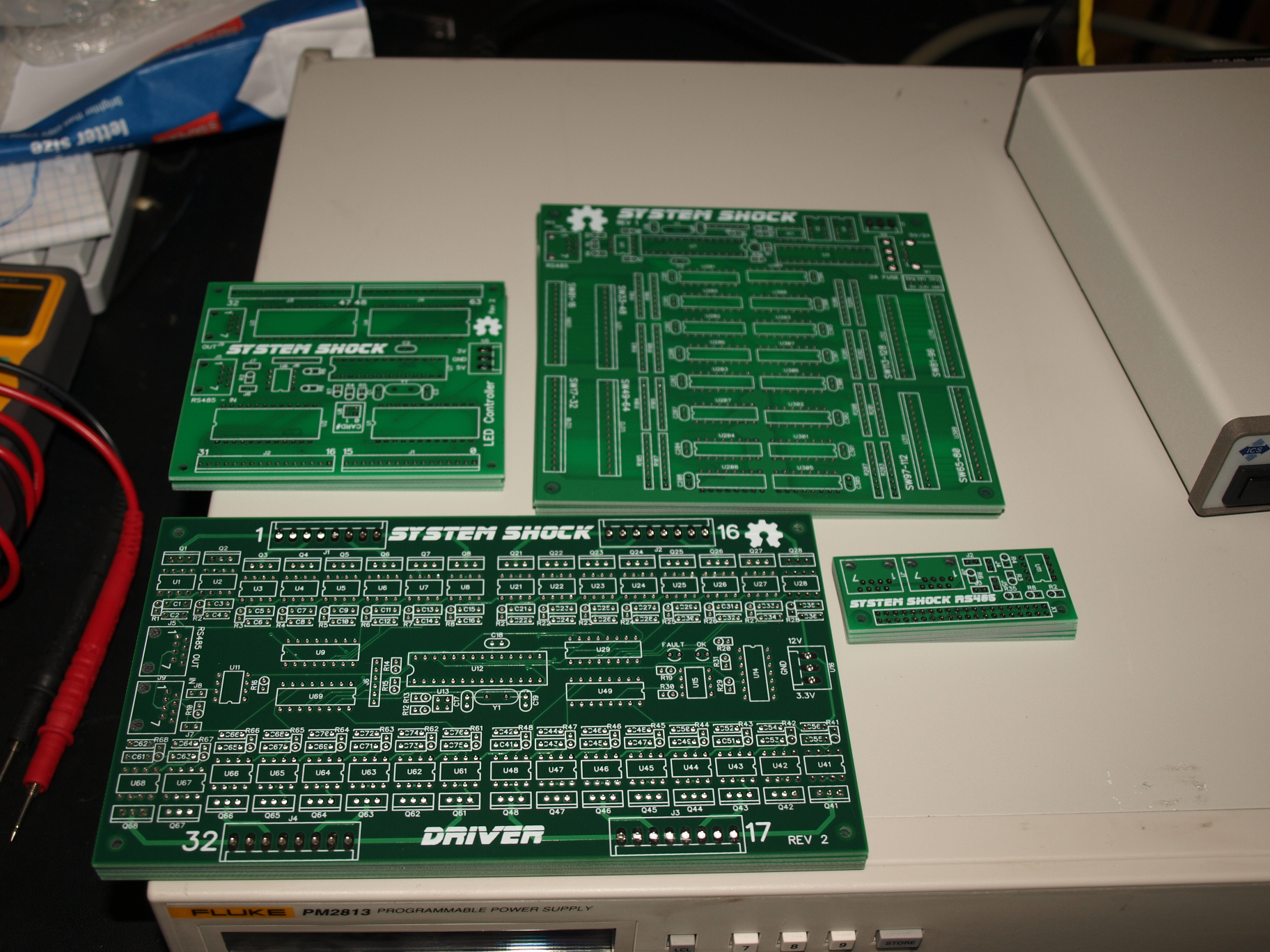
Top left is the 64 RGB LED insert driver
Top right is the master board, 128 switch inputs
Bottom left is the 32x FET driver
Bottom right is the wee raspberry pi comms board
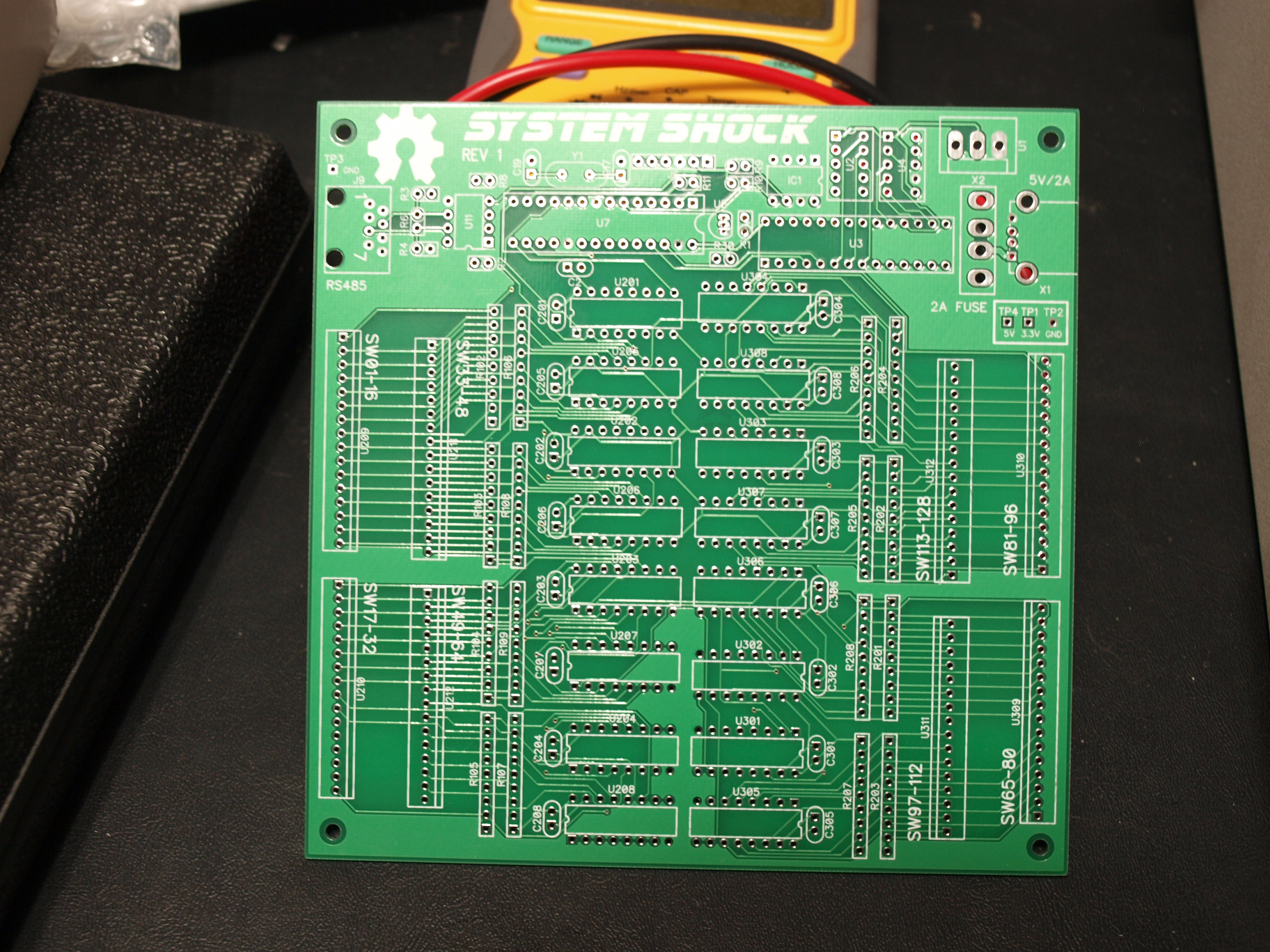
This is a closeup of the master board;
128 direct switch inputs, not charlieplexed/multiplexed. Has an eeprom for game settings, config, audits etc. There is a 2 digit error display, also a 48bit unique serial number on each board (would be good for ID'ing a game over the lan when hooked up to a central server to take in game scores, audits and such!) It has a USB plug that is fused with a 2A auto fuse to provide power to the raspberry pi board. This can be the rs485 master board, run the rules etc.
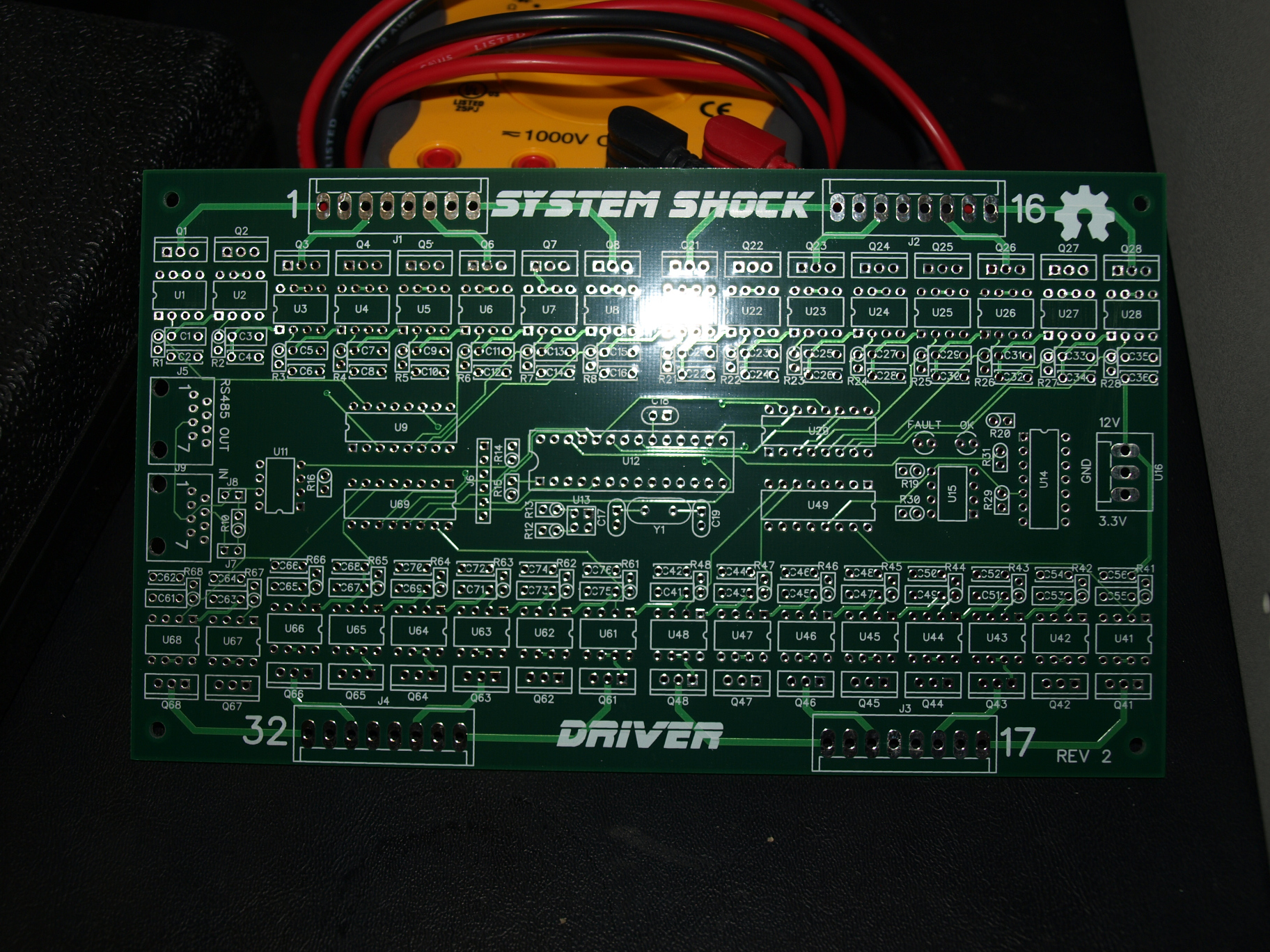
The FET driver, 32x individual fets. Can be configured to have up to 4 of these boards on the rs485 chain.
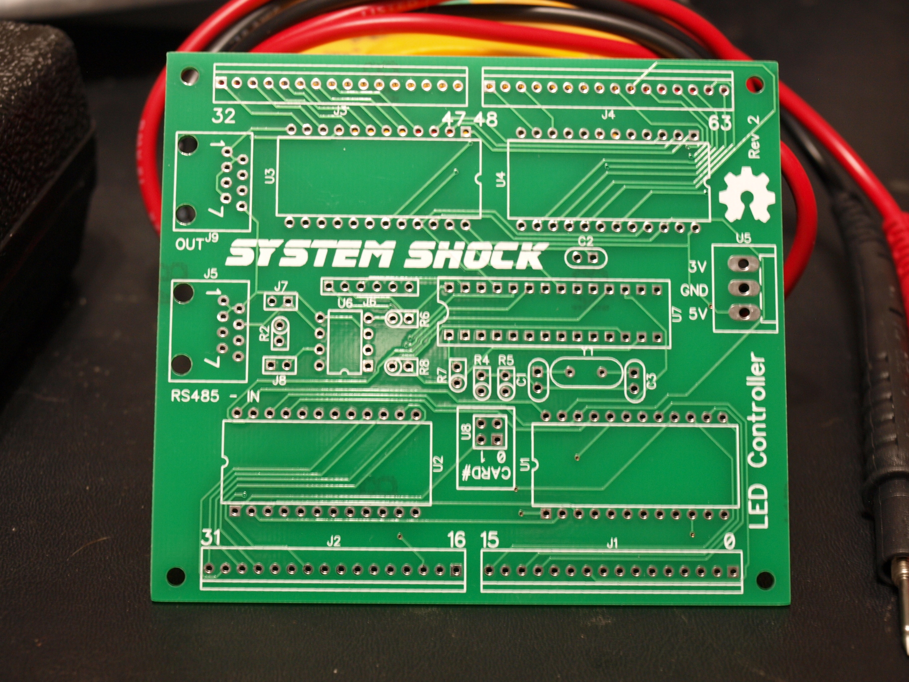
The RGB Insert driver, can drive 64 individual RGB LED's with complex light shows, fades, all running off its own cpu. Can have up to 4 of these boards for 256 RGB LED's. These are not chained, so if one goes down it does not take down a string of them.
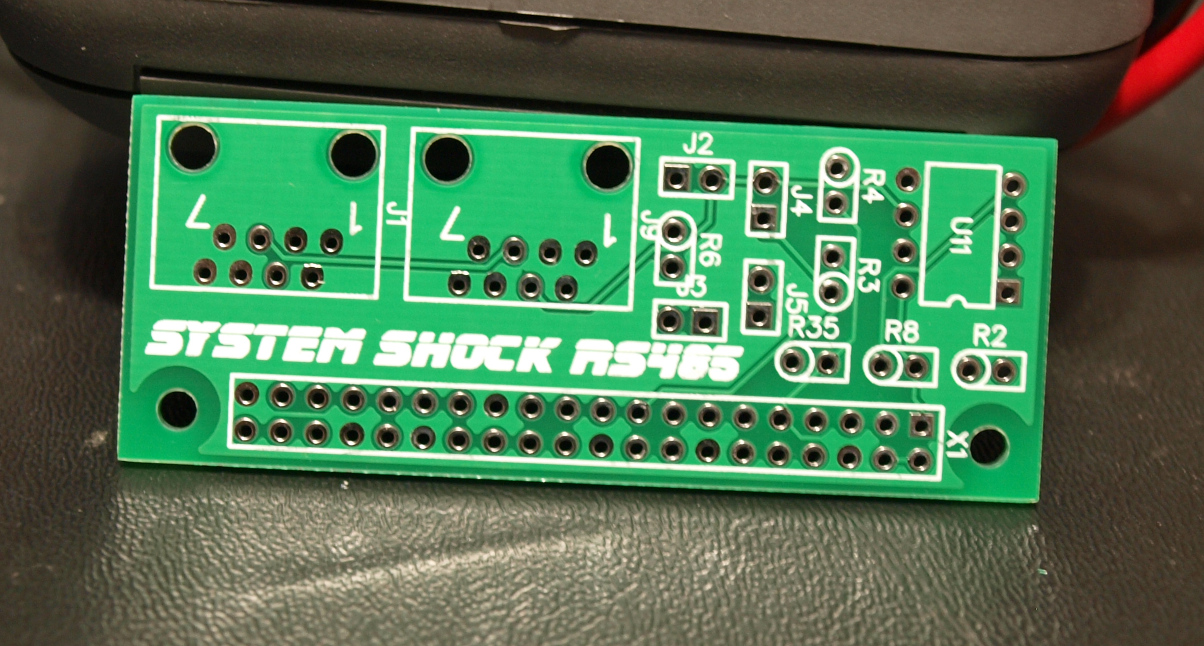
this wee board is the raspberry pi rs485 comms board, it also can be a master.
So I've said the word 'master' a few times, the original design had the switch board being the master, it ran the rules, read the switches and pumped the switch info out over the bus for all the child boards to snoop on and act opon, as well as sending other messages out over the bus. It would send messages to the RPI for doing audio/video like PLAY_SONG #1, SET_SCORE 123113300, etc.
but the pi comms board was the last board I did and I made it so I could use it outside of this project for other things, so that meant I could make it a master board as well.
With the pi being the master board, all the rules could move to here, off the switch driver board. that would make it more flexible for non C coders (the switch board is PIC32, and you need to write the rules in C), since the PI can run whatever (misson etc if I did the port). the only downside there is the switch board would be trying to 'control' the bus more than the master (PI) board would be, and software would need to be written to handle contention of having two boards being able to 'control' the bus.
Once I've soldered them all up and tested them, then I will push
it and the base code to my github. Im probably forgetting things
but its late and I'm tired lol one thing I became aware of later
was I'm hooked to the 3v3 pin on the pi, which can only supply
40ma or something, so that board may need a change to swtich 5v
down to 3.3v so I dont kill the 3v3 pi pin... and i may just go
back to my original design of tethering the pi directly to the
switch board with a good old idc cable so the pi is off the rs485
bus..
tags: PCB, System Shock
(dont include links in your comments.)